How to Quickly Implement a Qi Standard Compliant Wireless Charging System
For mobile devices, the charging process remains the final tether. While standards such as the Wireless Power Consortium (WPC) Qi specification help support higher power charging levels, developers still face multiple challenges when it comes to designing circuits, pc boards, and firmware to fully optimize wireless power transfer to mobile devices.
However, using devices and development kits from STMicroelectronics, developers can rapidly implement Qi-compliant systems able to meet the growing need for wireless charging at increased power levels.
This article describes how wireless power works, the role of wireless charging standards, and the challenges associated with design of compliant solutions. It then introduces the STMicroelectronics receiver and STWBC-EP controller, describes how their features address key wireless charging design requirements, and shows how developers can use them in wireless power designs.
The article concludes with a discussion of how developers can use the development kit and reference design for each device to significantly speed their own development efforts.
How wireless charging works
In a typical wireless charging system, a transmitter system powers a coil with alternating current, resulting in an oscillating magnetic field at the coil. Placed close enough to this primary coil, a receiver coil will resonate with the field due to magnetic coupling between the coils, leading to a corresponding alternating current in this secondary coil according to Faraday’s law of induction. By modulating the current at the primary coil and the load on the secondary coil, the transmitter and receiver can each encode data as variations in the coupled field, allowing them to exchange information needed to optimize power transfer.
Of course, actual application of this straightforward concept depends on careful design of optimized circuits for power generation on the transmitter side, power conversion on the receiver side, and precise control of the process on both sides (Figure 1). Even small differences in implementation of coil circuits or control methods can result in power transfer inefficiencies that can make the approach ineffective.
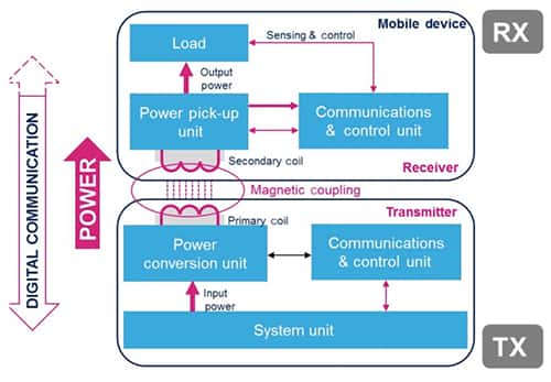
Figure 1: A typical wireless charging system uses the magnetic coupling between a primary coil in transmitter and a secondary coil in a receiver to transfer power and to exchange data.
Wireless power standards
To ensure optimal power transfer, wireless charging standards bodies such as WPC and the AirFuel Alliance provide detailed specifications designed to provide engineers with a consistent framework for wireless charging transmitters and receivers. Newer standards such as the WPC Qi 1.2 extended power profile add a further advantage with their support for higher power transfers at 15 W, as well as bidirectional communications capabilities designed to optimize transfer efficiency.
Implementing a standards-based wireless charging system can be challenging even for experienced developers. A design error or even a mismatched set of components can degrade power transfer efficiency below useful levels. Along with the difficulty of creating an optimized power transfer design, designers face a number of specific requirements associated with the protocol. For example, the Qi protocol specifies multiple states prior to the actual transfer stage (Figure 2).
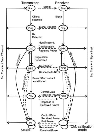
Figure 2: Standards use a series of precisely orchestrated stages such as these for the Wireless Power Consortium Qi standard to optimize power transfer between a transmitter and receiver.
In this protocol, a nearby receiver begins the process by pinging the transmitter and sending data to identify itself and its configuration to the transmitter. The transmitter and receiver then negotiate a power contract to establish a specific power transfer level. The transmitter and receiver might also engage in a calibration phase before finally beginning the actual power transfer phase. As power transfer proceeds, the receiver and transmitter can exchange information to ensure that power transfer remains both efficient and safe at the higher power levels available with the Qi 1.2 extended power profile.
In practice, implementation of this sophisticated protocol on an optimized hardware foundation presents multiple practical implementation challenges that can significantly increase design complexity and lengthen delivery schedules. For developers, however, the emergence of integrated wireless power solutions such as the STMicroelectronics STWLC33 receiver and STWBC-EP transmitter controller have largely removed barriers to implementation of compliant wireless charging systems.
Used in combination, the devices provide an optimized solution for 15 W charging systems compliant with Qi 1.2 extended power profile. Because each device conforms to the standard, developers can use each device by itself to implement individual wireless power receivers or transmitters able to work seamlessly with other Qi-compliant products. For both devices, the availability of a complete reference design and development board dramatically simplifies implementation of wireless charging. Just as important, the boards further speed deployment of these solutions because they both have already achieved WPC certification.
Flexible receiver
For building receiver systems, the STMicroelectronics STWLC33 is a 3.97 x 2.67 mm flip-chip device that integrates a complete wireless power RF front-end subsystem, low dropout (LDO) output regulator, and 32-bit Arm? Cortex? MCU. To minimize power dissipation, the device automatically adjusts LDO input voltage to minimize the LDO voltage drop and corresponding excess energy. Using the MCU's 32 Kbyte firmware memory, the device can perform both Qi 1.2 and AirFuel protocols to provide a standards-based wireless charging solution. During operation, the device automatically selects the Qi or AirFuel protocol depending on its measurement of the frequency and related signal data
Because of the STWLC33's integrated functionality, developers can implement a complete standards-based wireless power supply with only a few external components (Figure 3).
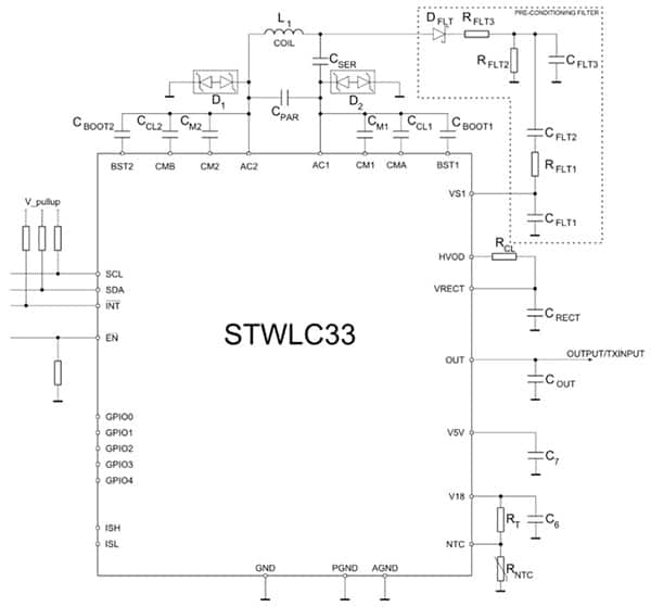
Figure 3: The STMicroelectronics STWLC33 integrates all the functionality required for wireless power receiver operations, requiring only a few additional external components including an optional pre-conditioning filter stage needed only for transmitter operations.
During operation in Qi mode, the device automatically performs each step in the Qi protocol described earlier. After completing the initial setup phases and entering power transfer mode, the device sends status information to the transmitter to optimize transfer – or independently terminates power transfer if it detects an error such as an overvoltage, overcurrent, or overtemperature fault. As a result, the device can operate as standalone supply.
Developers can also connect the device through its I2C interface or its configurable GPIO ports to a host processor. For example, developers might use a host MCU to disable the STWLC33 when the mobile device is away from any suitable charger, or send proprietary data packets back to the transmitter for specialized applications.
When combined with a host MCU, the STWLC33 can even serve as a wireless charger for another device such as a smartwatch or other low-power wearable (Figure 4).
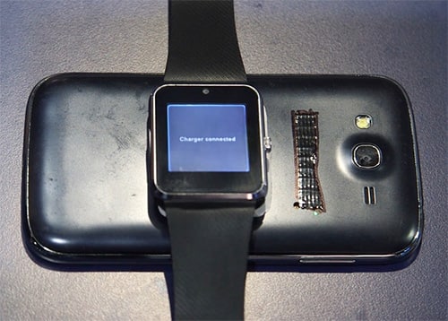
Figure 4: With its dual receiver/transmitter functionality, the STMicroelectronics STWLC33 allows developers to build mobile devices that can be charged with 15 W wireless power, and that in turn can wirelessly charge low-power devices such as wearables.
Other than the host MCU, this dual functionality adds no further design requirements. Developers can use the same external component configuration to operate the device as a receiver or transmitter.
Note that in receiver-only designs, the preconditioning filter highlighted in Figure 3 is not required. The device includes an internal switch that allows it to use the same coil for power reception and power transmission.
Although it includes the RF functionality required for transmitter operation, the STWLC33 is not loaded with the transmitter firmware in its default configuration. Still, developers can easily load the required code into the device from the host MCU using their shared I2C connection. With the addition of ST's transmitter firmware, the STWLC33 can provide a ready solution for some wireless charging applications. Nevertheless, its effectiveness in this role remains limited by the nature of the coil. The thin coils used to optimize reception result in transmitted power levels of only about 3 W.
Although developers can enhance transmitted power levels by adding an external coil, the additional required external switch, power boost, and control circuitry will quickly increase design cost and complexity. A better approach for higher power transmitter design would take advantage of ST's STWBC-EP wireless power transmitter controller.
Simplified transmitter design
As with the STWLC33 receiver, the STWBC-EP controller combines a full set of integrated hardware blocks with the firmware needed to implement the Qi standard. Although its unique features support Qi 1.2 15 W operation, the STWBC-EP remains compatible with receivers using the earlier WPC 5 V standard. For 15 W applications, however, the STWBC-EP and STWLC33 provide a comprehensive solution able to take full advantage of the power transfer optimization features built into Qi 1.2.
Unlike the STWLC33, the STWBC-EP levies increased integration requirements related to its use in higher level wireless power transmission systems. In its role as a controller, the device provides control signals intended to control external power components used to drive a wireless charging coil. Consequently, designers typically need to add external power circuits, such as a DC-DC converter, to boost voltage to the levels required to properly energize the coil.
With the STWBC-EP, developers can use the device's built-in support and output control signals to operate a typical DC/DC boost converter. Here, developers would connect the STWBC-EP's DCDC_DRV output pin to a buffer transistor that would in turn drive an STMicroelectronics MOSFET used as the power switch in a familiar boost converter topology (Figure 5).
Figure 5: The STMicroelectronics STWBC-EP eliminates the complexity associated with designing power control circuits, but developers must still create the corresponding power circuits such as this STL10N3LLH5 MOSFET based DC-DC boost converter that is required to energize the power coil.
In this configuration, the STWBC-EP's built-in control algorithm uses the device's CS_CMP input pin to monitor inductor current and its VTARGET pin to monitor output voltage. The algorithm automatically adjusts output voltage by comparing the feedback voltage level at its CMP_OUT_V pin with a reference voltage (DCDC_DAC_REF, not shown) that developers can program to meet specific power transfer requirements. Besides this typical boost converter configuration, developers can even use the STWBC-EP to monitor inductor demagnetization (DEMAGNET pin in Figure 5) while operating the converter with quasi-resonant switching to improve efficiency in low load operations.
Although the STWBC-EP helps simplify design of power circuits, developers can nevertheless find that the detailed design requirements associated with these power circuits work against rapid development of wireless charging subsystems. With its development kits, however, ST provides a shortcut for deployment of designs using the STWBC-EP and STWLC33.
Wireless charging development aids
For STWBC-EP-based designs, the STMicroelectronics kit and associated reference design offers a complete wireless transmitter design, already certified as compliant with the WPC Qi 1.2 standard. Similarly, STMicroelectronics’ kit and reference design provide a full solution to wireless power receiver design using the STWLC33.
Because of the additional complexity associated with transmitter power circuits, the STEVAL-ISB044V1 reference design is particularly helpful for rapid development of wireless charging systems. For example, along with the coil boost converter design discussed earlier, the STEVAL-ISB044V1 reference design shows the corresponding circuit required to drive a wireless charging coil such as the with a half-bridge power stage (Figure 6).
Figure 6: The STMicroelectronics STWBC-EP wireless power firmware uses a handful of device ports to monitor and control the half-bridge power circuit driving the power transmitter coil.
As with the boost converter circuit, the coil circuit uses STWBC-EP control signals (UPBL and DNBL) to control gate drivers for the STL10N3LLH5 MOSFETs.
Even with these schematics in hand, developers can face further complications during pc board physical design. Optimized power transfer requires careful consideration of pc board routing and component placement. STMicroelectronics helps designers through this critical development phase by providing guidelines that relate the power circuit design with its corresponding pc board physical layout (Figure 7).
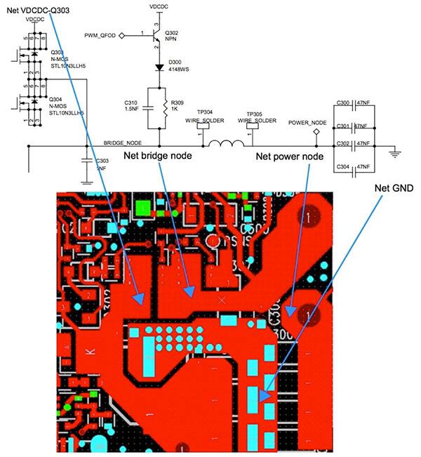
Figure 7: STMicroelectronics helps designers identify critical issues in pc board physical design through a series of guidelines that relate circuit design to physical design of the half-bridge power circuit in this case.
Firmware configuration
As mentioned earlier, circuit and pc board design are only part of the equation for successful implementation of wireless charging systems. For standards-based systems, effective power transfer depends on strict adherence to protocols specified in those standards. Because the STWBC-EP and STWLC33 each include firmware that implements those standard protocols, developers can quickly implement wireless power subsystems, particularly when using the STEVAL-ISB044V1 and STEVAL-ISB042V1, respectively, as the basis for transmitter and receiver designs.
Although the firmware for each device is delivered in binary format, ST gives developers broad visibility into the run-time characteristics of each device. While operating the STEVAL-ISB044V1, for example, developers can closely monitor operation of the STWBC-EP-based system through a graphical interface (Figure 8). Separate tabs let developers monitor and control operation of the circuit at each stage of the Qi protocol.
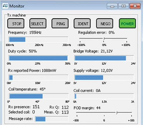
Figure 8: Developers can monitor each stage of the Qi power protocol using the STMicroelectronics graphical interface.
For finer control of operations, developers can modify configuration parameters through additional screens (Figure 9). After modifying parameters, developers can click the "push to target" button to write the new parameters to the STWBC-EP and observe the results. After evaluating different configuration options, the next step is to save the updated configuration and write the final settings to the device. Developers can similarly observe and configure the STWLC33 through its own screen options.
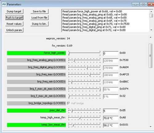
Figure 9: Using target device, observe the result, and update the target with the desired final configuration. a series of screens in the STMicroelectronics graphical interface, developers can easily modify configuration parameters, push them to the
Conclusion
Wireless power is rapidly emerging as a required feature as users look to cut the final cord to their mobile devices. Although wireless power standards have helped accelerate acceptance, implementation of wireless power designs based on these standards has remained a significant challenge for developers. With the availability of integrated wireless power solutions, many of the traditional barriers to implementation have fallen.
Using the STMicroelectronics STWBC-EP and STWLC33, along with their associated development kits, designers can rapidly implement Qi compliant wireless power transmitters and receivers able to meet growing demand for wireless charging at increased power levels.
